panStamp IoT Evaluation
Introduction
This is the evaluation of the panstamp low-power wireless modules. The panstamp modules are based on the CC430F5137 chipset. The chipset is a very neat device; Ti combined the very popular MSP430 microcontroller with the CC110L wireless chip. The device package is very low-power (1.0uA in sleep mode), and has a foot-print of 7.75mm x 7.75mm. The device only requires a low-pass filter along with some bypass components.
The panstamp modules are configured using the Arduino IDE. More information can be found here.
Evaluation Setup
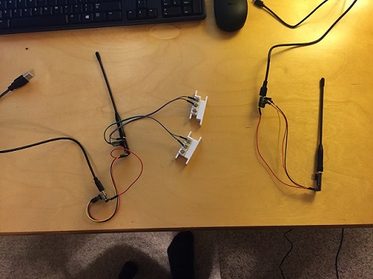
The evaluation setup is comprised of two panstamp modules:
- A module configured in transmit beacon mode. Module transmits a packet periodically
- A module configured in receive only mode and transfers the received packet to a host computer using an FTDI USB Serial Module UB232R
The RF radio has been configured to maximize distance by decreasing the data rate. In addition, the transmitter output power is configured to the highest level (12dBm). Summary of RF Radio settings:
- Tx Output Power 12dBm
- Data Rate (bandwidth) 4800 bps
Please note, I used the UB232R to source power to the panstamp module for this evaluation. Therefore, the modules are not configured to operate in low-power mode.
Software/Firmware
The test was originally developed using Python to post-process the received packets on the USB serial port. I’ve recently purchased a home version of LabVIEW through MakerHub, so I ported the packet processing software to a user friendly GUI. The below table describes the source code found in this repository:
- Arduion_Panstamp_Source
- simpleRPi_Rx.ino : The receiver source code
- simpleRPi_Tx.ino : The transmitter source code
- python
- listen_beaconRx.py : Script to read packets on the serial port and display the data on the terminal
- LabVIEW
- panStamp_beaconRx.lvproj : LabVIEW project file with VI's
LabVIEW GUI
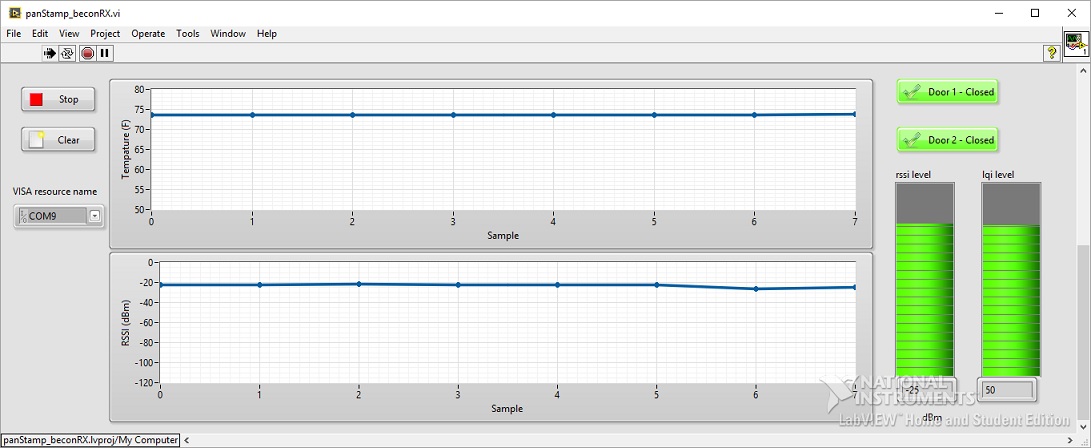
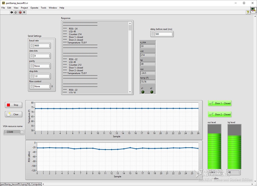
The LabVIEW GUI includes several different interfaces, such as a text version of the received packet. The GUI was minimized to hide all the various GUI modules. The below two images is the minimized window, and the second is the full GUI with all the front panel components:
LabVIEW GUI minimized window
LabVIEW GUI showing all front pannel components
Results
I was able to achieve a reliable wireless communication link at a distance around 200 meters. The receiver module was located in my office and the transmitter was located in my backyard of my home. I plan to use the CC430F5137 chipset for my home automation project. I’m currently using the panstamp modules to prototype the design and plan to design a custom board with an integrated USB and an Ethernet port using the ENC28J60 device (serial to Ethernet device).